Friction stir welding
Process principle
The basic principle of FSW is to soften the material by frictional heat generated between the material surfaces and a rotating tool (Fig. 1).
In the conventional butt joint set-up, the components to be joined are rigidly clamped on a backing plate. A rotating tool, consisting of a profiled pin and a shoulder, is forced down into the material until the shoulder meets the surface of the workpieces. The material in the close surrounding of the tool is thereby frictionally heated to temperatures where it is easily plasticised. As the tool moves forward, material is stirred from the leading to the trailing edge of the pin. Behind the pin, the solid state joint is formed. A distinction is made between the advancing side of the weld (AS – the side where the tool rotation direction is the same as the welding direction), and the retreating side (RS – the side where the tool rotation direction is opposite to the welding direction), as also indicated in Fig. 1.
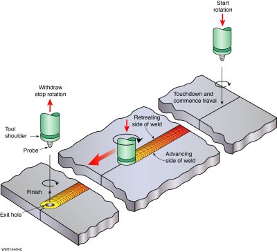
Fig. 1: Schematic representation of the friction stir welding process

Fig. 2: Milling machine, modified for friction stir welding (Source: UCL-PRM)
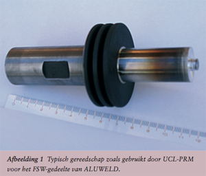
Fig 3: FSW tool
A friction stir welded joint consists of various zones involving different microstructures and mechanical properties, as shown in Figure 4. The heat affected zone is the most distant from the joint line and is not deformed, but the dissolution and coarsening of precipitates (precipitation hardenable alloys) or dislocation density reduction (cold worked alloys) due to the thermal cycles influence the mechanical
properties of this zone. The thermo-mechanically affected zone (TMAZ) is not only heated but also plastically deformed, while the nugget is highly deformed. Contrarily to the TMAZ, the nugget has undergone dynamic recrystallisation.
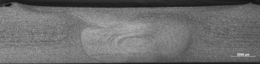
Fig. 4: Dwarsdoorsnede van een FSW lasverbinding
The FSW technique has proven to be particularly successful in production on low melting point alloys, with the most important ones from an industrial viewpoint being the aluminium alloys. For most of these alloys, common tool steel can be used for the FSW tool, and high production rates can be achieved with the technique in combination with outstanding joint properties and good visual aspect.
The main advantages of FSW applied to aluminium alloys are the following:
- Fully automatic welding in all positions at high productivity and constant quality;
- Single pass welding of thicknesses down to 0,5 mm up to 65 mm;
- Successful joining of alloys or alloy combinations that cannot be fusion welded;
- Low thermal distortion, limited softening;
- Limited weld seam preparation (no need to remove the oxide layer);
- No consumables, filler materials or shielding gases;
- No UV radiation, spatter, weld fume, high electric current, electromagnetic fields;
- High energetic efficiency;
- Limited maintenance and wear parts;
- Relatively flat weld surface.
The most commonly cited limitations for a conventional tool FSW machine are:
- Large process forces (high stiffness of the machine, rigid clamping equipment);
- Exit hole remains after tool withdrawal;
- Relatively high demands in terms of joint fit-up;
- Relatively high investment cost + licence cost;
- Other weld flaws are possible if the process is not properly optimised.
The main welding parameters for the friction stir welding process are:
- Welding speed (expressed in mm/min);
- Tool rotation speed (in rev/min or rpm);
- Tool geometry (including tool cooling) and tilt angle;
- Plunge tool depth (in the case of displacement control) or plunge force (in the case of force control).
Additional influence factors (which are often much more difficult to control) are weld gap, workpiece thickness variation and mismatch, clamping equipment and stiffness of the FSW machine. Note that also the welding ratio is often used (expressed in rev/mm), which is defined as the tool rotation speed divided by the welding speed. The higher this value, the more heat is introduced into the workpiece (hence the higher the resulting heat input should be).
dr. ir. Koen Faes