INNOJOIN: Development and evaluation of advanced welding technologies for multi-material design with dissimilar sheet metals
Context
Global trends force the industry to manufacture lighter, safer, more environmentally friendly, more performant and cheaper products: the machine construction sector is aiming at more performant machine components, for the consumers and construction products, increased integration of functionalities provides a competitive advantage and in the transport sector, weight reduction is pursued. Combining conventional metals with others or even new materials, offers designers solutions where a design consisting out of one material fails. A multi-material design exploits the material with desired properties for each part of the component or product.
Multi-material design is however hindered by challenges in the field of joining technology. The prerequisite for the production of such multi-material components is the availability of suitable joining technologies.
New developments
During the last years, new processes have appeared on the market which have the potential for welding of dissimilar sheet metals. Currently, there is little objective knowledge available concerning the technical suitability of the use of these processes for certain material combinations of products, nor about the possible increase of the productivity or about the achievable weld quality, and thus about the economic advantage that these innovative processes can offer for the industry.
Project goals
There is a range of joining processes available allowing dissimilar material combinations, each with their own technical and economic merits. The capabilities and limitations of these joining processes need to be understood and known to maximise joint and component performance and to enable companies to use these processes for realising components with a higher added value.
Up to now only very little independent application-oriented research has been carried out regarding the feasibility of the proposed processes for industrial applications. This knowledge is also essential to assist companies during the decision process whether or not to implement a specific joining process, or for the selection of a particular process (and its equipment), ensuring smooth implementation.
Project description
Techniques covered in the project
Resistance welding processes
Resistance spot welding equipped with intermediate layers (process tape) in between the electrodes and the workpieces to be welded is a further development of the conventional resistance spot welding process. The presence of the intermediate layers (tapes), available in different alloys with different electrical and thermal conductivities, enables to gain substantially more control on the heat input the process. This increases the range of successful material combinations of the spot welding process.
- For more information click here
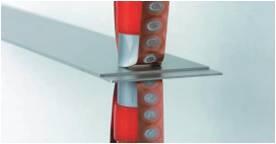
Figure: Resistance spot welding with process tape
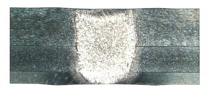
Figure: Resistance spot welding of materials with different widths
(AlMg3 - widths: 1 - 2 - 3 mm)
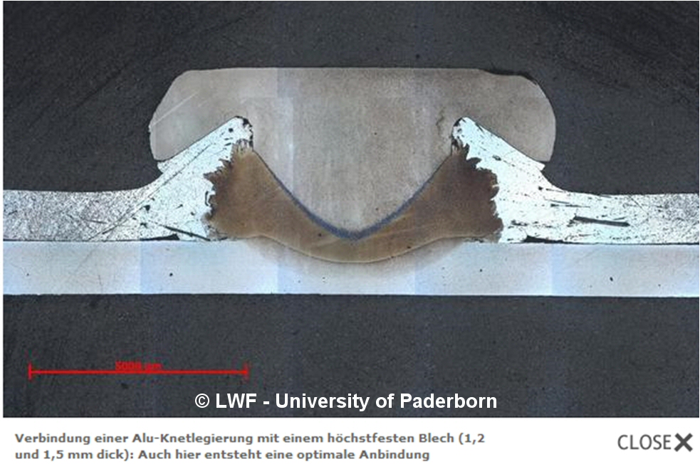
Resistance element welding combines both thermal and mechanical joining principles, by creating a metal bond between an auxiliary joining element and the lower joining partner. After creating of a pre-hole, the auxiliary element, called weld rivet, is inserted in the hole. One electrode is lowered onto the rivet and the other is positioned onto the base sheet. Pressure and electric current are applied simultaneously. Heat generated by electrical resistance causes a weld nugget formation in the contact zone between weld rivet and base sheet and creates the connection.
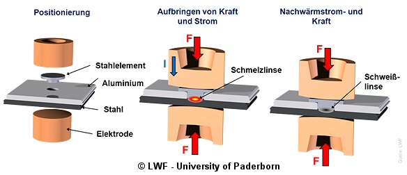
Figure: Resistance element welding
Arc element welding (stud welding with an auxiliary joining part)
In arc element welding, a short auxiliary joining part is used. The top sheet must be perforated. There is no direct joint between the top sheet and the bottom sheet, but the auxiliary joining part guarantees the fixing of the top sheet onto the carrier sheet in a mainly form-fitting and partial force-fitting joint. A welded joint is created only between the auxiliary joining part and the carrier sheet.
The welding processes available in this case are drawn-arc stud welding and the process variants with initial-contact capacitor discharge.

Figure: Arc element welding (stud welding with an auxiliary joining part)
Friction welding processes
Like resistance element welding, friction element welding also combines thermal and mechanical welding principles by the use of an auxiliary joining element. The main difference is the generation of the necessary process heat, which is done by friction. The frictional heat causes a plasticisation of the cover sheet and allows to penetrate the material without any pre-hole operation or melting. Trials have been performed to join aluminium to steel and aluminium to polymers
 |
|
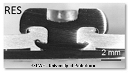
Figure: Friction element welding (Bron : EJOWELD-project)
Source: Sampro
Friction spot welding
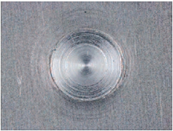
A three-component tool comprising a pin, sleeve and clamping ring is used to join two or more sheets in the overlap configuration. The clamping ring initially fixes the sheets against a backing plate while the pin and sleeve begin to rotate in the same direction while pressing on the upper surface (Figure a). The rotating pin and sleeve are moved in opposite direction to each other (one is plunged into the material while the other moves upwards), creating a cavity where the plasticised material through frictional heat is accommodated (Figure b). After reaching the pre-set plunge depth, the pin and sleeve return to their initial position forcing the displaced material to completely refill the keyhole (Figure c). Finally, the tool rotation is stopped and the tool is withdrawn from the joint leaving a flat surface with minimum material loss (Figure d).
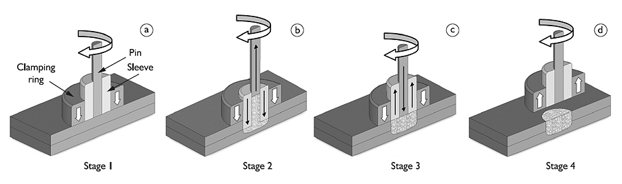
Figure: Friction spot welding (© SLV München)
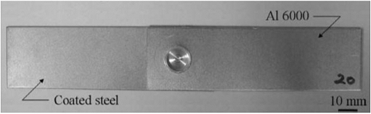
Figure: Friction spot welding (© SLV München)
 |
 |
Figure: Friction spot welding (© SLV München)

Figure: Friction spot welding machine available at BWI
- More information about friction spot welding
Ultrasonic welding
This is a solid-state welding process in which a connection is accomplished by local generation of high frequency vibration energy. The tip of the sonotrode is in direct contact with one of the workpieces to be welded.
The other workpiece is attached to the anvil so that it cannot move during welding. The system sends small, linear, cyclic movements to the tip of the sonotrode, called ultrasonic vibrations. This vibration creates frictional heat between the materials to be welded. This ensures that the materials are brought into a plastic state, causing the upper component to be joined with the lower component.

Figure: Sonotrode for ultrasonic welding (Source: Belgian Welding Inst.)

Figure: Ultrasonic weld of coper to aluminium (Source: Schunk Sonosystems)

Figure: Ultrasonic seam weld of coper to aluminium (Source: Schunk Sonosystems)
Friction stir welding and friction stir spot welding
Friction stir welding (FSW) is a solid-state joining method meaning that no melting occurs during the process. A rotating tool is pushed into the material. The frictional heat generated by this penetration action softens the workpiece material to a plastic condition making it flow around the pin. The tool is then moved along the joint line. One of the variants of standard FSW is friction stir spot welding (FSSW), where no longitudinal movement is applied but only a rotation and up-and-down movement.
Although this process was originally developed for joining non-ferrous materials, machine and tool material developments have enabled to apply this welding method to material combinations like aluminium to steel or copper to aluminium.
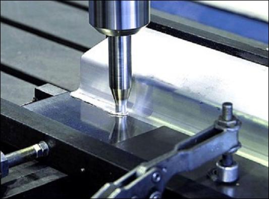
Figure: Friction stir welding
Arc welding processes
Laser beam welding (continuous or pulsed)
In laser welding, the beam is concentrated very locally making this welding method a high power density process. Due to the local heat input, deep welds can be produced at high heating and cooling rates. These process characteristics make it possible to produce precision joints with a narrow heat-affected zone and limited workpiece deformation after welding. The high heat-exchange rates also have a positive effect when joining dissimilar metals.
Different methods in laser beam welding exist such as continuous and pulsed welding. The continuous laser is typically standard, while the pulsed laser makes it possible to very accurately control the heat input and weld penetration.
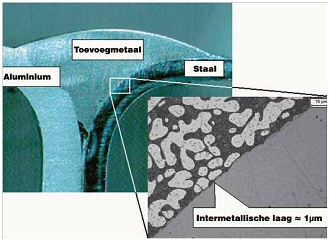
Figure: Aluminium-steel connection realised with “fluxless laser brazing”. (Source: Corus)
Elektromagnetisch puls lassen
This joining technology uses electromagnetic forces for deformation and joining of workpieces. A capacitor bank is charged, when the required amount of energy is stored in the capacitors, it is instantaneously released into a coil, during a very short period of time (typically 10-15 µs). The discharge current generates a very short but high magnetic pressure, which causes one workpiece to impact with the other workpiece. The deformation takes place at a very high velocity, like in explosive welding. The explosive deformation force is however created in a safe way, by using electromagnetic forces generated by an induction coil.
 |
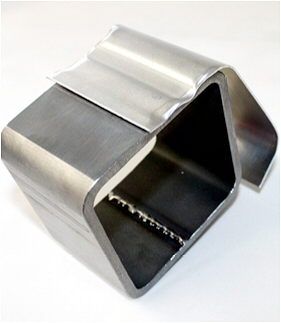 |
Figure: Electromagnetic pulse sheet welding
(Source: M. Kashani - Tokyo Metropolitan College of Technology & PSTproducts)
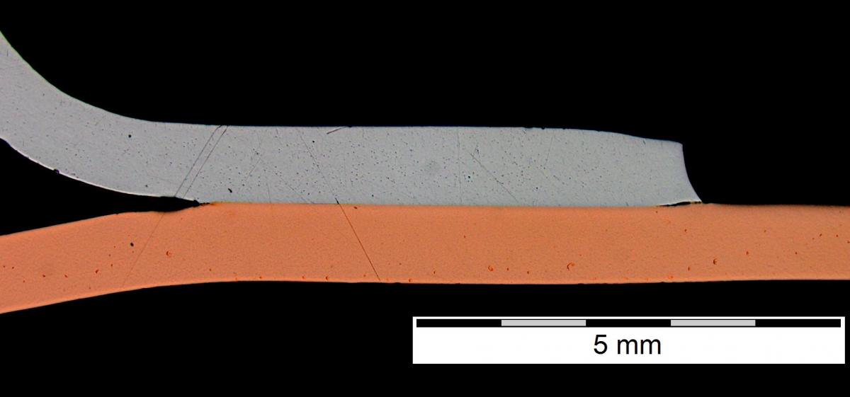
Figure: Electromagnetic pulse weld of copper to aluminium

Figure: Electromagnetic pulse weld of copper to aluminium - Detail
Results
- Click here to download the summary of the project results