MetalMorphosis : Electromagnetic pulse technology for novel hybrid metal-composite components in the automotive industry
Lightweight materials and joints between metals and composites
Driving forces behind the trend towards lightweight materials and joints between metals and composites
Trends towards increasing vehicle weight are arising due to continuous and stringent demands imposed on the improvement in safety (crash, passenger, fire/electrical, advanced braking systems), passenger comfort (seating, interior space, in-vehicle climate control) and electronic systems (electrical supply, control in vehicle information/entertainment). Therefore, the need to reduce the vehicle weight and fuel consumption, has resulted in a gradual substitution of the materials present in vehicles. A reduction in the quantity of cast iron and plain carbon steel in and their replacement by high performance steels (stainless and high strength steels), light alloys (primarily aluminium) and plastic and plastic composites is pursued. These materials allow to mitigate the trend for increasing vehicle weight. In particular, the requirement for weight reduction promotes composites as key materials for the present and future. The major advantage of these materials is their high ratio between their stiffness and strength and their low density. In this way, composites offer the possibility to achieve significant weight reductions and accordingly lower fuel consumption. However, an important drawback of composites is their brittleness. Joints between composites and metals are therefore required to obtain the desired structural properties.
Research and production models of lightweight materials
Composites are currently advancing in research projects related to automotive applications. European industrial application-oriented research regarding the structural performance of hybrid lightweight vehicles was carried out in the SuperLightCar project. In the framework of this project, design concepts were developed which allowed to achieve both a weight reduction up to 30% and a cost reduction. Figure 1 shows an example of manufacturing such a car using different lightweight materials. In the past years, several production models on the market were introduced, which illustrate the concepts developed in research projects such as the SuperLightCar project. An example of this the BMW i8: a new generation of electrical cars in which the majority of the structural components are manufactured from carbon fibre-reinforced composite and aluminium (see Figure 2).
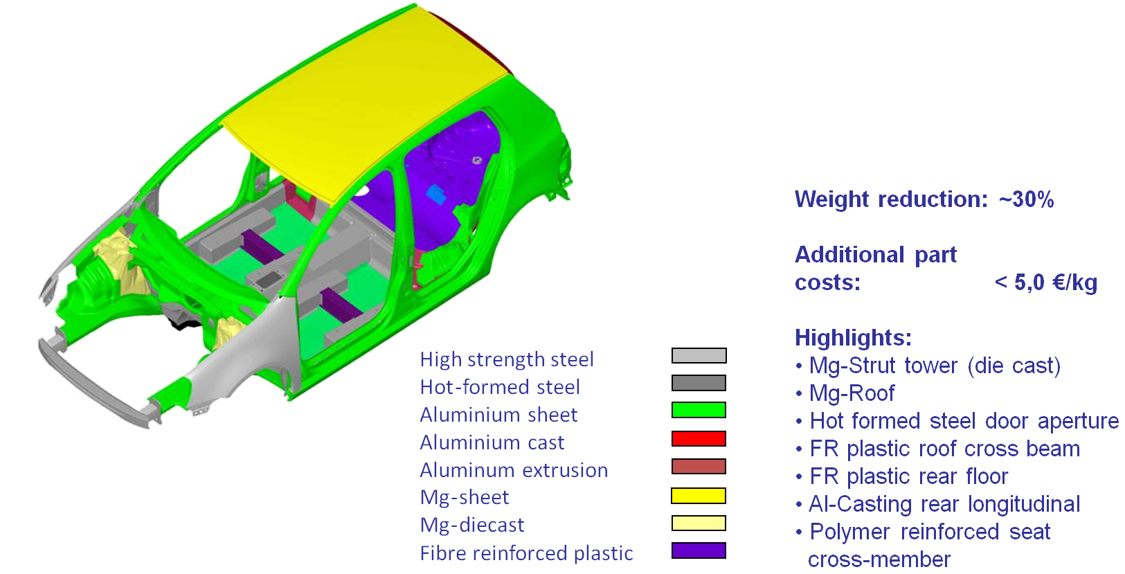
Figure 1: Results of the SuperLightCar project: percentual weight savings and additional costs for manufacturing a car in lightweight materials [1]
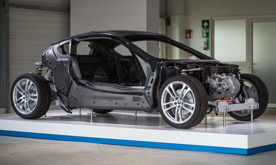
Figure 2: BMW i8 – Electrical car made of carbon fibre-reinforced composite and aluminium [2]
Composites and their joining techniques
Composites for hybrid components
The most important mechanical property of composites is their high strength to density ratio. Composites thus offer the possibility to achieve impressive weight reductions for the next generation products. At the same time, they also exhibit outstanding mechanical properties. The structure of composites consists of two constituent materials. The first constituent is a reinforcement material that contributes to the mechanical and physical properties of the composites, allows for the transfer of tensile forces and thus enhances the matrix properties. The second constituent is a matrix material that maintains the position of the reinforcement, by supporting the reinforcement materials. It furthermore allows for the transfer of compressive forces and shear stresses. Both constituents combine their properties in a synergetic manner, hence achieving characteristics significantly different from the individual constituents. It is therefore important to select a proper combination of the constituents, with fibres as reinforcement material and polymers as matrix material. Since automotive components are usually subjected to impacts throughout their entire life cycle in a vehicle, composites with a high impact resistance are required.
Although composites are currently used in the automotive industry, they only represent 7,5% of the total vehicle in volume. Moreover, they are typically involved in components that are more suitable for cosmetic purposes, rather than structural performance. Glass fibre-reinforced plastics make up the majority of applications available today, but have limitations terms of strength. Recent activity indicates that there is much more interest today in composites that provides additional structure performance. In particular, carbon fibre-reinforced composites (CFRP) exhibit the highest potential for lightweighting in automotive applications. This is because they can provide weight savings greater than 60%, compared to the use of steel. Nevertheless, the current limitations of carbon fibres are their high costs and long processing times.
Despite the recent developments and technologies for manufacturing advanced composites, it is not expected that composites will fully substitute the current materials employed in vehicles. Instead, novel hybrid metal-composite structures will be developed and hence cost-effective processes will be required for the assembly of composite and metal materials. The hybridisation formulation indeed allows to construct structures where the shortcomings of the individual materials are compensated (both technical and economic) and where their benefits mutually enhance, making a synergic effect. Figure 3 illustrates the strength versus density of different types of material classes.

Figure 3: Strength versus density for different material classes
Joining technologies for metal-composite products
Two main methods for joining metals to composites are adhesive bonding and mechanical fastening. However, they are developed for a specific application in mind and result in high operational costs. The resulting joints furthermore exhibit limited mechanical properties. Other joining technologies for hybrid metal-composite components include welding processes such as ultrasonic welding, friction and laser welding. However, these techniques are in a developmental phase and more research is required to ascertain the feasibility and durability of the resulting joints. Finally, hybrid joining comprises the combination of two or more joining methods intending to enhance the joining quality. But because of their hybrid nature, these methods present not only the advantages of each single process, but also their associated drawbacks. In conclusion, the currently used methods in industry for joining metals to composites are usually application-specific, presenting high operational costs and limited mechanical properties.
Project goals
The global objective of the European research project MetalMorphosis was the development of a new range of hybrid metal-composite components, based on the innovative electromagnetic pulse joining process. Currently, this technology is used for joining similar and dissimilar metals. In this project, its scope was expanded towards fast and cost-effective joining of composites and metals, which will improve the joint and product performance. In this way, the disadvantages associated with the traditional joining methods will be decreased or even eliminated. The project therefore demonstrated that the electromagnetic pulse technology is a valuable alternative for realising high-performance joints and will allow its transfer to the industry in the coming years. The resulting specific automotive components target the pressing need for reduced weight and fuel consumption, and hence match current automotive market challenges.
More specifically, the MetalMorphosis project pursued the following objectives:
- To develop new joining processes for composites and metals, based on the electromagnetic pulse technology, for high-performance joints of composites with metals for sheet and tubular applications,
- To gain fundamental knowledge concerning the properties of the joints (strength, ductility, microstructure, ...) and their applicability in the automotive industry,
- To increase productivity and reduce cost for hybrid components by using the novel electromagnetic pulse technology: joining operations are performed faster and more efficient and robust.
- To cope with the requirements of compatibility, due to the more environmental-friendly process.
The MetalMorphosis project comprised six technical work packages, which aimed at research related to the specification -, joining- and characterisation activities. Apart from that, a separate work package dealt with the manufacturing of three specific demonstrators, relevant for the automotive industry.
In the framework of this project, the Belgian Welding Institute investigated the applicability of electromagnetic crimping of tubular composite to metal workpieces. In particular, this article discusses the developed joining concepts and the research performed concerning the hybrid metal-composite tubular and sheet connections. Furthermore, the development of a hybrid metal-composite brake pedal and shock absorber using the electromagnetic pulse technology is illustrated. The development of these two demonstrators was carried out in collaboration with industrial partners, and served to validate the developed novel joining concepts and design strategies at an industrial level.
Project description
Working principle of the electromagnetic pulse technology
The electromagnetic pulse technology (also known as electromagnetic pulse forming, crimping and welding) is a highly innovative automatic production technique which use electromagnetic forces to deform and join products. Since this advanced technology does not make use of heat to realise a connection, it offers attractive possibilities for joining of dissimilar materials, compared to traditional joining techniques.
It is a high-speed deformation process that uses a pulsed magnetic field for contactless forming of metals. The basic principle of the process is shown in Figure 4. A tool coil is placed over the workpieces which should be joined, but does not make any contact. The energy stored in a capacitor bank is then discharged rapidly through the coil. The magnetic field produced by the coil generates eddy currents in the adjacent workpiece from metallic material with good electrical conductivity. These currents, in turn, produce their own magnetic field. The forces generated by the two magnetic fields oppose each other. Consequently, a repelling force between coil and workpiece is created, that accelerated the outer workpiece towards the inner workpiece at a large velocity. This results in a permanent deformation, without springback of the workpieces. Therefore, the forces generated can for example be used to collapse a tube with high velocity onto an internal workpiece, or to form, cut or perforate a sheet using a special-shaped die. Under precisely controlled conditions and process parameters, a solid-state weld can be realised. During the welding cycle, large amounts of electrical energy are discharged in a very short time period. Some equipment systems can even discharge 2 million Ampère within 100 μs.
Figure 5 shows the possible variants of the electromagnetic pulse forming for joining sheet and tubular work pieces. Depending on the arrangement of the tool coil and workpiece, tubular profiles can be expanded or compressed or sheet metals can be formed. Because only the outer workpiece to be deformed as described must be made out of electrical conductive material, this process can be used for joints of similar or dissimilar materials. Even metallic and non-metallic material joints with high strength performance can thus realised.
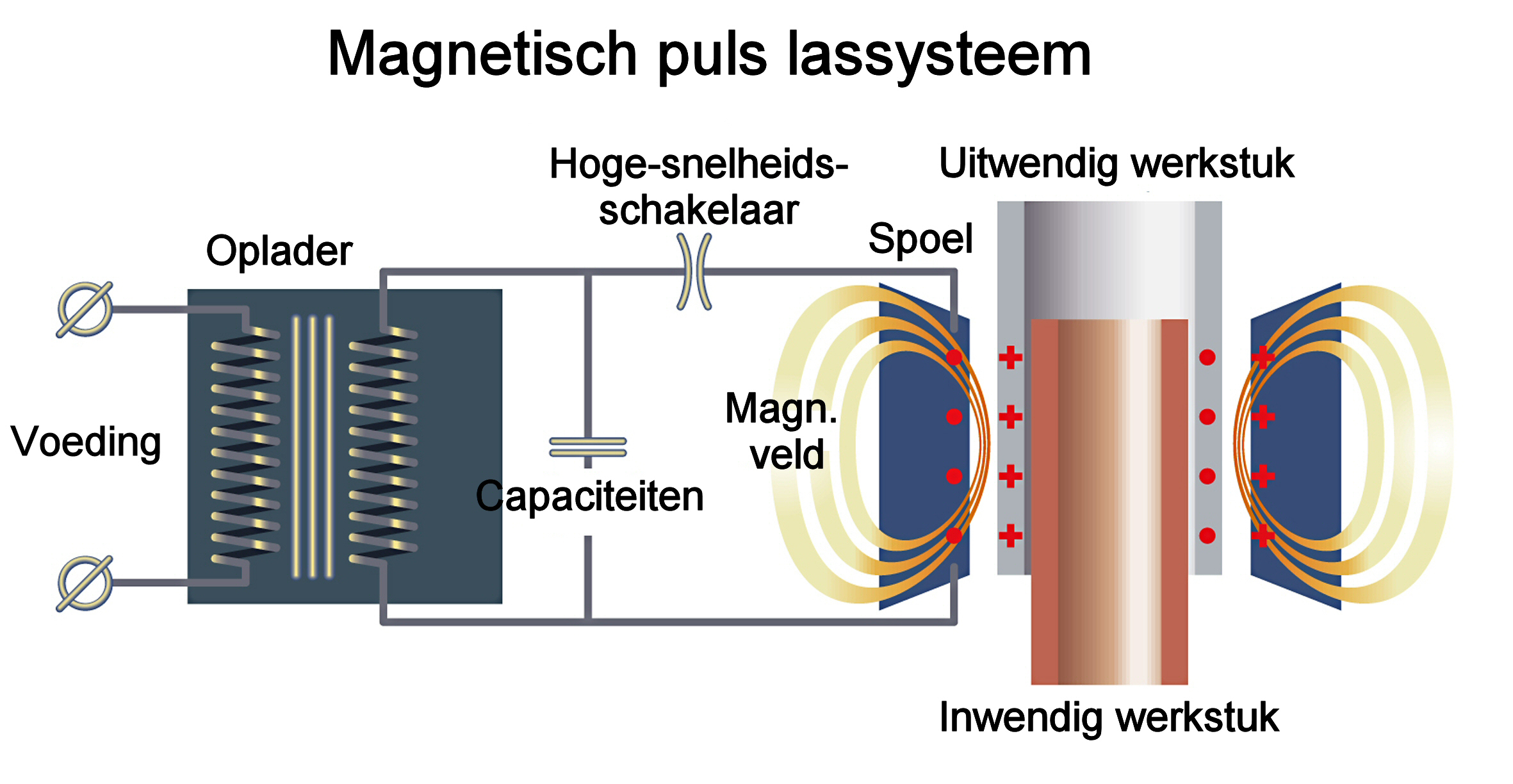
Figure 4: Principle of the electromagnetic pulse technology
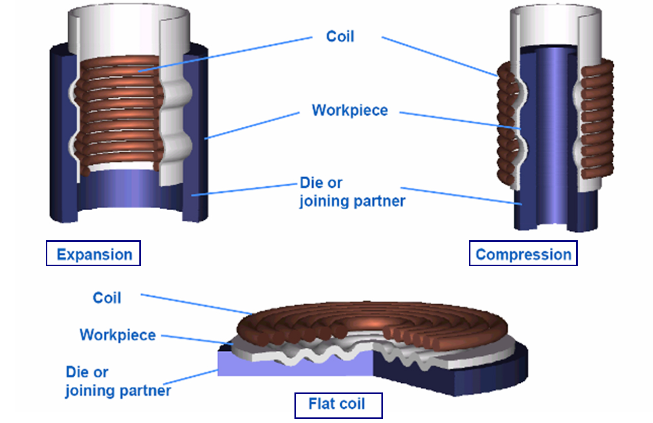
Figure 5: Possible variants of electromagnetic pulse forming for joining sheet and tubular work pieces (Source: Institut für Umformtechnik und Leichtbau, Technische Universität Dortmund, Germany) [3]
Specific advantages related to this technology make it particularly suitable for fast and cost-effective joining of non-weldable materials, like dissimilar materials joints:
- Compared to conventional welding processes, the electromagnetic pulse technology is a “cold” joining process, because the outer workpiece only heats up through Eddy currents and plastic deformation. Therefore, since no heat is employed to join materials, neither a heat affected zone nor a thermal-induced degradation is created, so that properties of the resulting joint are not deteriorated,
- Parts can immediately be unloaded after joining and further processed with standard equipment. This is because the temperature increase is very local (in the order of 50 μm), and the workpieces reach no more than 30-50°C at the surface of the outer workpiece,
- High repeatability due to the accurate adaption of the applied forces, which is the basis for constant joint quality,
- Automatic process and high production rates,
- Ecological joining process, as no heat, gas, or smoke is produced.
In the MetalMorphosis project, 3 variants of the electromagnetic pulse technology were applied. For tubular joints, electromagnetic pulse crimping was employed and for sheet joints, electromagnetic pulse welding and electromagnetic riveting was used.
Electromagnetic pulse crimping
Joints manufactured by electromagnetic forming can be classified into two categories, according to the dominating mechanism against an external load, namely joints based on interference fit or on form fit. Interference fit joints are created by a plastic deformation of one and an elastic deformation of the other joining partner. As a result, friction and interference stresses between both joining partners are generated. In contrast, form fit joints are manufactured by forming one joining partner’s material into an undercut (for example a groove) of the other joining partner. In this way, the joint is locked against an external load (mechanical interlock). Within the MetalMorphosis project, various innovative joining concepts were designed for both interference and form fit joints.
Electromagnetic pulse welding
Electromagnetic pulse welding is used for joining a metal workpiece to a composite workpiece in which a metal is embedded. If the workpieces are impacted at a high velocity and under a certain angle, a jet is created along the materials’ surface prior to contact. This jet removes surface contaminants, after which an intensive local plastic deformation and local heating takes place, resulting in bonding. Because the process takes place in a very short lapse of time, heating is not enough to generate a temperature increase in a wide area and hence no significant heat affected zone is present.
Elektromagnetisch riveteren
In electromagnetic riveting, the electromagnetic pulse is used to accelerate a punch over a few millimeters up to a significant high speed (10-100 m/s). In this way, a magnetically accelerated rivet can join a hybrid metal-composite sheet with a metal sheet. The working principle is illustrated in Figure 6. Because riveting is a process with a short cycle time, up to 60 rivets per minute, it is essential to work at the lowest possible discharge energy through the coil. Otherwise, for temperature reasons, it is not possible to decrease the cycle time below 4-5 per minute (typical speed for electromagnetic forming processes).
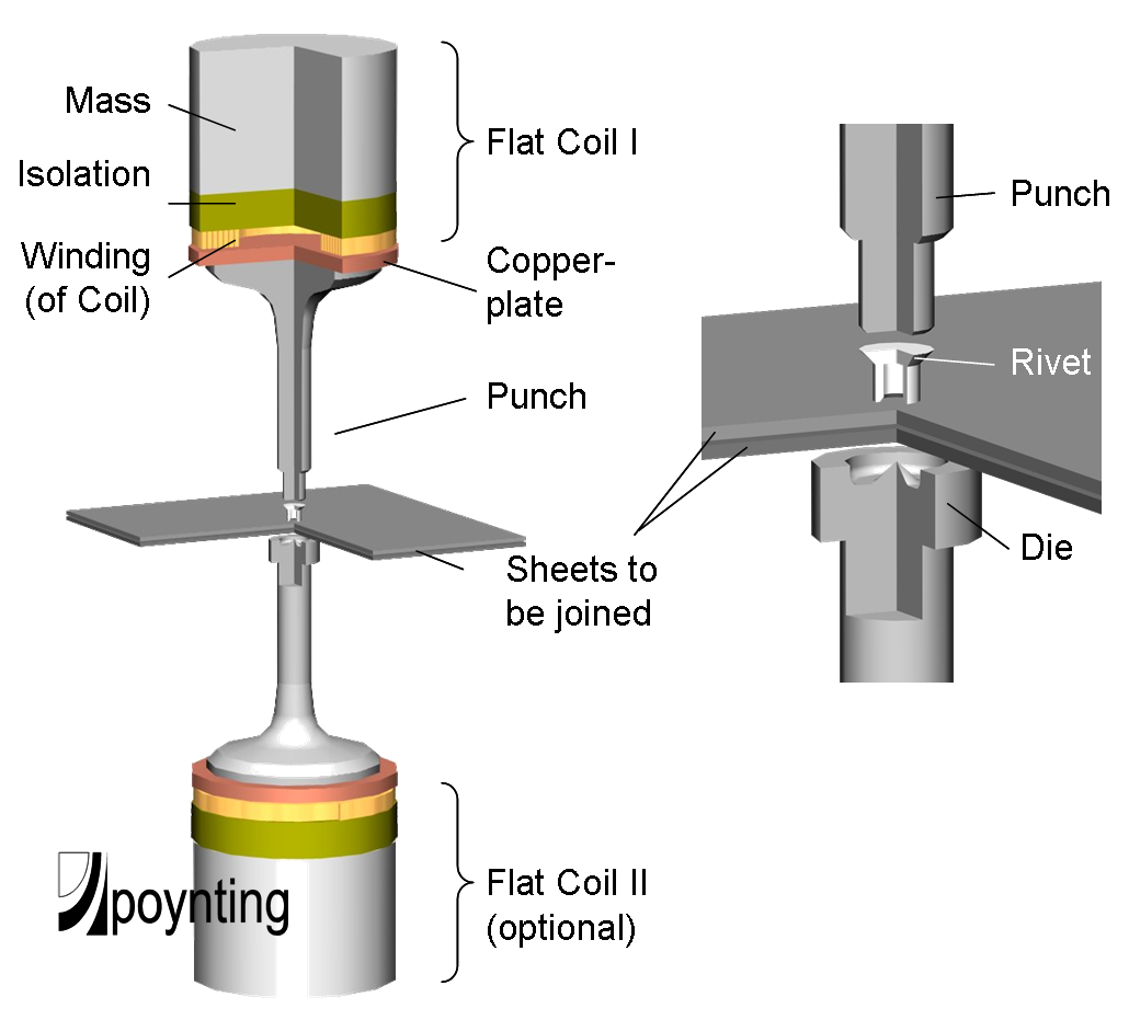
Figure 6: Principle of electromagnetic riveting for joining of sheet workpieces (Source: Poynting GmbH, Germany) [4]
Results
Hybrid metal-composite tubular joints
The hybrid metal-composite tubular workpieces were manufactured using electromagnetic pulse crimping. First, a few composites were selected which are relevant for the automotive industry. Several joining concepts were subsequently developed to join the aluminium tube (EN AW-6082 T6) onto the composite. Finally, the resulting metal-composite tubular joints were examined for their transferable force and failure mode during tensile testing.
Selected composites
Since automotive components are usually subjected to impacts throughout their entire life cycle within in a vehicle, a high impact resistance of the composite is required. Additionally, the composite should be resistant against high temperatures. Polyamides are suitable matrices, as they can be modified to improve their impact behaviour. They furthermore exhibit high mechanical properties at elevated temperatures and a high wear resistance. Carbon fibres are one of the strongest and stiffest fibres available on the market. Moreover, they exhibit a very low density, which results in an excellent ratio between their mechanical properties and weight.
Based on these requirements, the following types of composites were selected: continuous carbon fibre-reinforced epoxy, continuous glass fibre-reinforced epoxy (EP GC22), and short glass fibres-reinforced polyamide (PA6.6 GF30). The fibre volume fraction and the length of the fibres (short or continuous) were varied, in order to obtain the different types of composites. Composites in both rod- and tube-like form were selected.
Joining concepts for hybrid metal-composite tubular joints
Different joining concepts were developed and evaluated for electromagnetic pulse crimping of metal tubes onto the selected composites. These joining concepts were based on interference fit joints and form fit joints, as discussed previously. Different test series were identified based on either the geometry of the composite workpiece or on the gap distance between the aluminium tube and the composite workpiece. This distance was created by varying the wall thickness of the aluminium tube or by modifying the outer diameter of the composite workpiece. Within each test series, the discharge energy level, necessary to create the joint, was varied.
The resulting hybrid metal-composite tubular joints were first visually examined, after which their transferable force and failure mode were recorded during tensile testing. Moreover, a comparison of the behaviour of the different metal-composite joints was made within one and the same joining concept. A selection of some joining concepts and the experimental results achieved will be discussed hereafter.
First joining concept: based on interference fit
In a first joining concept, based on interference fit, an aluminium tube (EN AW-6082) was joined onto a composite rod, by electromagnetic pulse crimping. The plastic deformation of the aluminium tube and the elastic deformation of the composite rod generated friction and interferences stresses, which contribute to the joint strength. Different test series were conducted, based on the variation in the gap distance between the aluminium tube and the composite rod. This distance was created by varying the wall thickness of the aluminium tube or by modifying the outer diameter of the composite workpiece. Within each test series, the discharge energy level, necessary to create the joint, was varied.
Figure 7 illustrates the cross section of such a crimp connection, based on interference fit, between an aluminium tube and a continuous carbon fibre-reinforced epoxy rod.
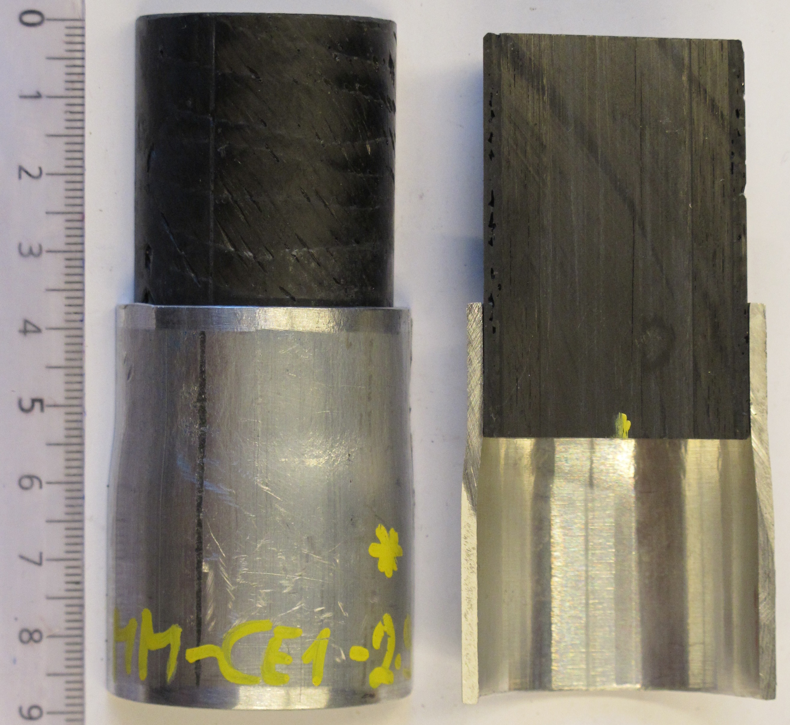
Figure 7: Cross section of a crimp connection, based on interference fit (1st joining concept), between an aluminium tube (EN AW-6082) and a continuous carbon reinforced epoxy rod (Source: Belgian Welding Institute, Belgium) [5]
Second joining concept: based on form fit
In a second joining concept based on form fit, an aluminium tube was joined onto a grooved composite rod and tube, by electromagnetic pulse crimping. In this way, the aluminium tube can deform into the groove of the composite, through which a mechanical interlock between both workpieces is achieved. This can possibly result in a higher transferable force. It is however necessary to evaluate whether or not the integrity of the groove was maintained during the crimping operation. Different test series were identified, based on the geometry of the groove, namely the depth, radius and angle of the groove.
Figure 8 shows a cross section of such a crimp connection based on form fit, between an aluminium tube and a continuous glass fibre reinforced epoxy tube (EP GC22). Figure 9 presents a cross section of a similar crimp connection, between an aluminium tube and a short glass fibre reinforced polyamide rod (PA6.6 GF30).
|
Figure 8: Cross section of a crimp connection, based on form fit (2nd joining concept) between an aluminium tube and a long fibre glass reinforced epoxy tube (Source: Belgian Welding Institute, Belgium) [5]
|
Figure 9: Cross section of a crimp connection, based on form fit (2nd joining concept) between an aluminium tube and a short fibre glass reinforced polyamide rod (Source: Belgian Welding Institute, Belgium) [5] |
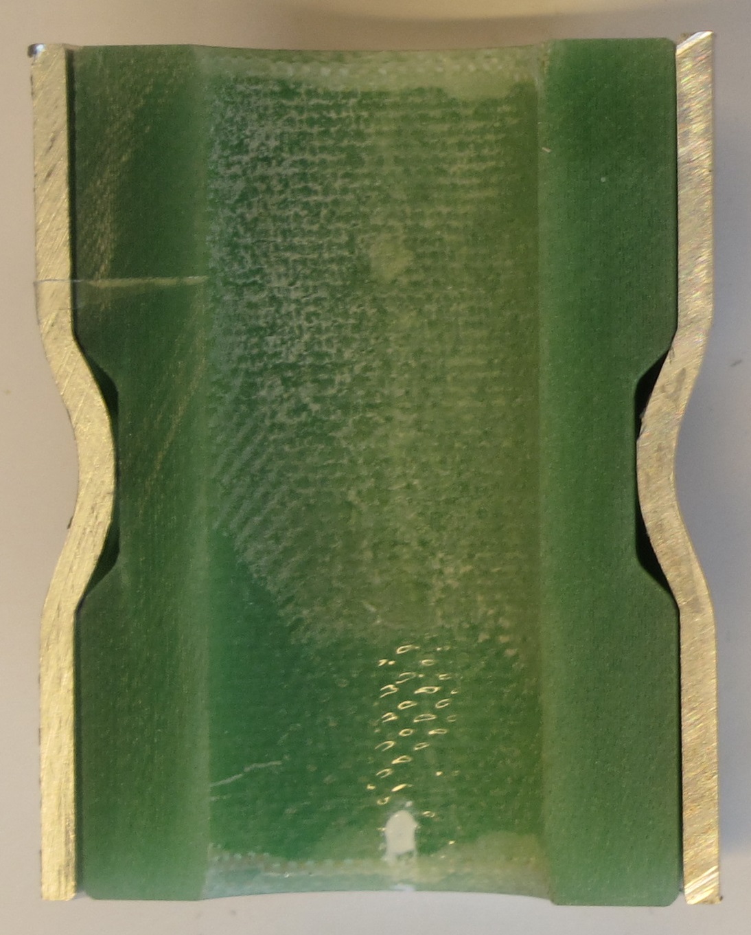

Figure 10 compares the transferable forces achieved for crimp connections between an aluminium tube and short glass fibre-reinforced polyamide rod (PA6.6 GF30 - Figure 9) on the one hand, and a long glass fibre-reinforced epoxy tube (EP GC22 - Figure 8) on the other hand. For each composite type, several test series were conducted, in which the groove geometry was varied. Based on the results achieved, it was concluded that the crimp connections between aluminium tubes and a continuous glass fibre-reinforced epoxy tubes achieved a higher range of transferable forces than the crimp connections between aluminium tubes and a short glass fibre-reinforced polyamide rods. This can partially be explained by the high tensile strength of the continuous glass fibre-reinforced epoxy tubes (typical tensile strength of 285 MPa), compared to the tensile strength of the short glass fibre-reinforced polyamide rods (152 MPa). In general, a higher transferable force was achieved at a higher discharge energy level and a larger deformation of the aluminium tube into the groove. This deformation is amongst others determined by the groove geometry.
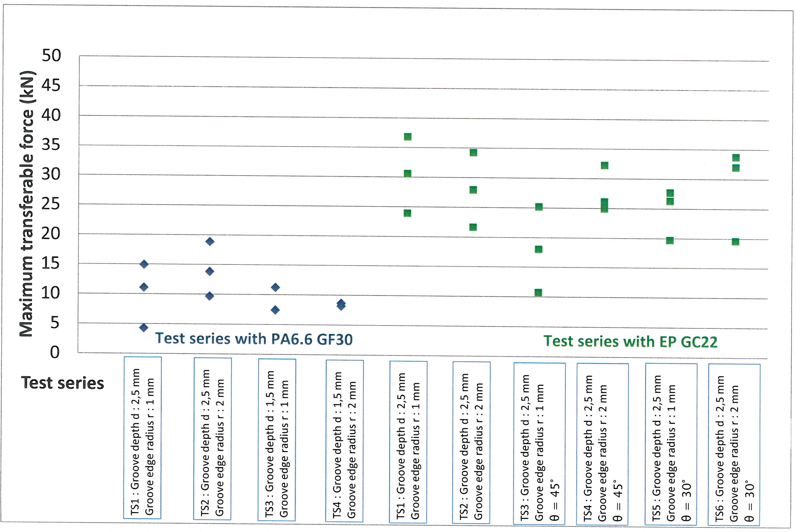
Figure 10: Comparison of the maximum transferable forces achieved for crimp connections between aluminium tubes and short glass fibre reinforced polyamide rods (PA6.6 GF30) and aluminium tubes and continuous glass fibre reinforced epoxy tubes (EP GC22), with different groove geometries, according to joining concept 2 (Source: Belgian Welding Institute) [5]
Two different failure modes during tensile testing of the crimp connections were observed. In the first failure mode, the diameter of the aluminium tube enlarged, after which the tube bent out of the groove. Nevertheless, no fracture of the aluminium tube occurred (see Figure 11). In the second failure mode, the aluminium tube bent out of the groove and subsequently cracked along its longitudinal direction (see Figure 12).
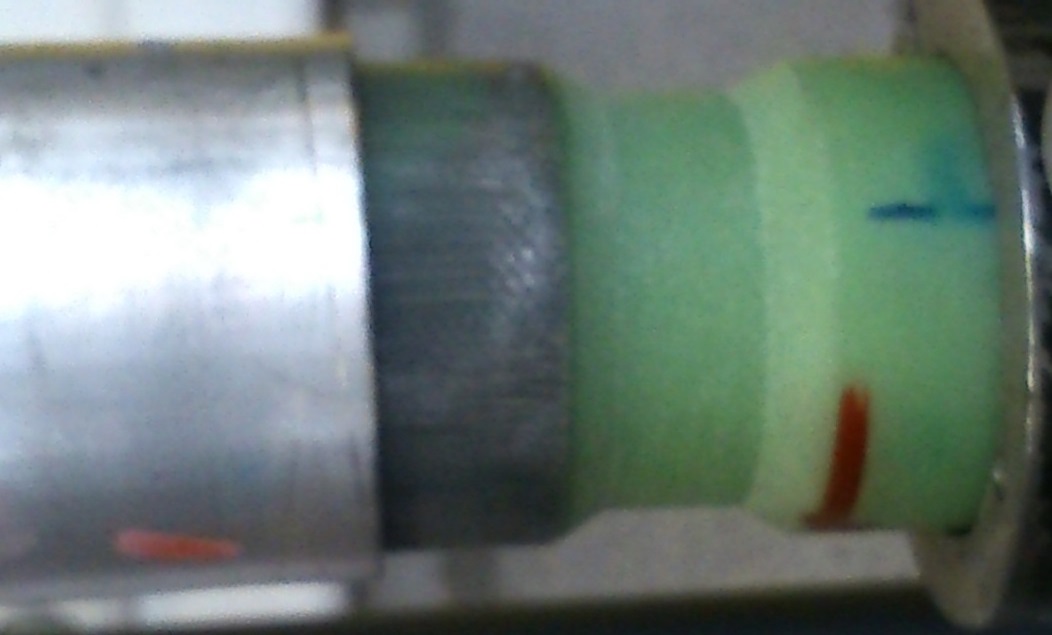
Figure 11: First failure mode of a crimp connection between an aluminium tube and a continuous glass fibre reinforced epoxy tube (EP GC22) (Source: Belgian Welding Institute, Belgium) [5]
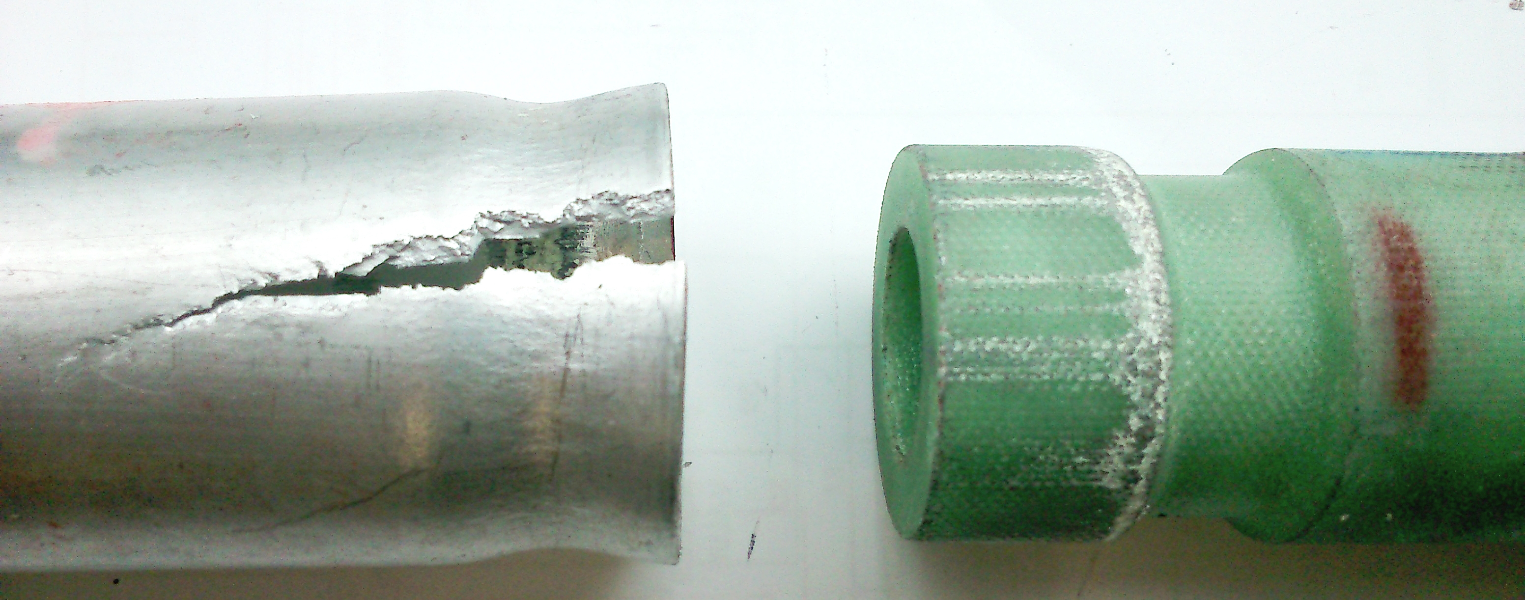
Figure 12: Second failure mode of a crimp connection between an aluminium tube and a continuous glass fibre reinforced epoxy tube (EP GC22) (Source: Belgian Welding Institute, Belgium) [5]
Third joining concept: based on form fit
In a third joining concept, also based on form fit, an aluminium tube with an internal screw tread was joined onto a composite rod, by electromagnetic pulse crimping. In this way, the teeth of the internal screw thread created a mechanical interlock between both workpieces. Different test series were identified, in which the gap distance between the aluminium tube and the composite rod was varied. This gap distance was created by adjusting the outer diameter of the composite rod. Within each test series, the discharge energy level was varied.
Figure 13 illustrates the cross section of such a crimp connection between an aluminium tube with an internal screw thread and a short glass fibre-reinforced polyamide rod (PA6.6 GF30). The indentations of the internal screw thread of the aluminium tube into the short glass fibre reinforced polyamide rod is shown in Figure 14.
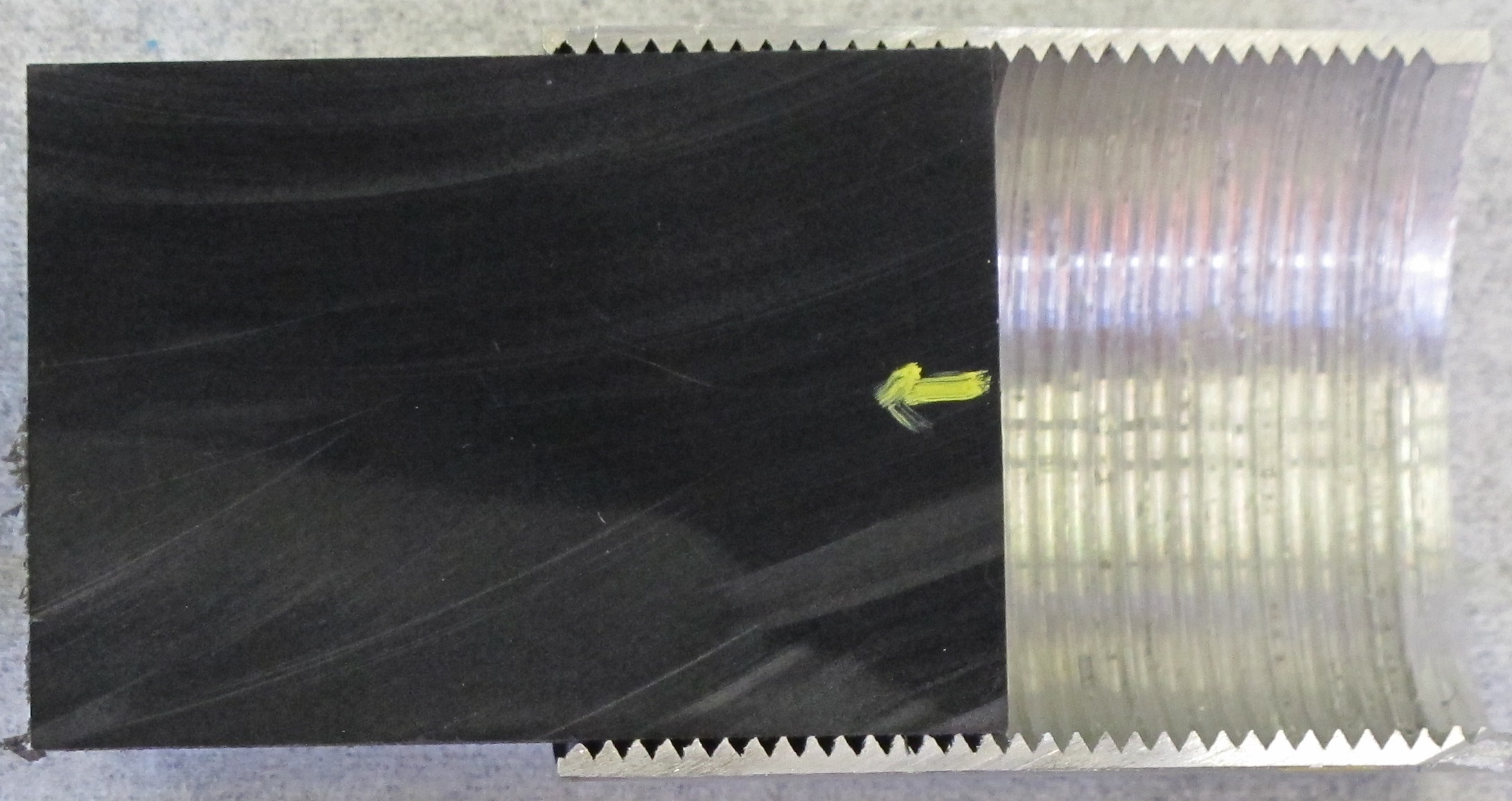
Figure 13: Cross section of a crimp connection based on form fit interference (3rd joining concept) between an aluminium tube and a short glass fibre reinforced polyamide rod (Source: Belgian Welding Institute, Belgium) [5]

Figure 14: Indentations of the screw thread inside the aluminium tube into the short glass fibre reinforced polyamide rod (Source: Belgian Welding Institute, Belgium) [5]
Hybrid metal-composite sheet joints
The hybrid metal-composite sheet joints were manufactured using electromagnetic riveting and electromagnetic pulse welding. Figure 15 shows an example of electromagnetic riveting of a metal sheet (aluminium EN AW- 6016, thickness of 1,2 mm) to a sandwich sheet. The latter consists of two metal layers (steel DC04, both thicknesses of 0,5 mm) with a composite intermediate layer (carbon fiber reinforced plastic, thickness of 0,8 mm). The cross section shows a good spreading of the rivet in the joint, as well as a deformation of the carbon fiber material without visible fiber damage. Furthermore, it was determined that a rivet with a lower hardness resulted in a higher transferable force, compared to a rivet with a higher hardness.
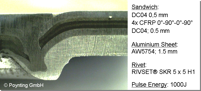
Figure 15: Cross section of a sheet joint between an aluminium plate and a hybrid steel-composite plate, using electromagnetic riveting (Source: Poynting GmbH, Germany) [4]
Demonstrators
Three specific demonstrator parts were fabricated, which were representative for potential industrial applications and satisfied the requirements set by the industrial partners. In this way, the acquired knowledge regarding the developed joining concepts and design strategies were validated at an industrial level. Two demonstrator parts, namely a brake pedal and a shock absorber, will be discussed in detail hereafter.
Hybrid metal-composite brake pedal
Toolpresse is a Portuguese company that engages in stamping metal parts, welding and assembly of metal sets and subsets, hence producing parts mainly aimed at the automotive market. Amongst others, it manufactures brakes pedals that are currently completely made out of metal. In the MetalMorphosis project, a redesign of the current brake pedal was performed, in which a steel component of this automotive pedal was substituted by a composite component and subsequently joined onto the remaining metal components.
The following objectives, set by Toolpresse, were taken into account when the hybrid metal-composite brake pedal was fabricated:
- Reduction of the risk of serious lower limb injuries of the drive in a frontal collision through the use of composite materials, whilst simultaneously ensuring compliance with legal requirements and international statutory,
- Reduction of the weight of the brake pedal assembly, compared to the weight of the existing components made entirely of metal. The state-of-the-art steel brake pedal has a weight of 0,6 kg. The partial replacement by a composite should result in a 15% weight decrease,
- Reduction of the cost and production time, due to the smaller number of operations and components. The introduction of the composite material should also preferably be accomplished without product cost increase. A total product cost increase of € 1 to 2/kg saved weight is however allowable.
The prototype and the actual demonstrator of the hybrid metal-composite brake pedal are illustrated in Figure 16 and Figure 17, respectively. It was fabricated by crimping an aluminium square tube onto two short glass fibre-reinforced polyamide (PA6.6GF 30) workpieces containing a groove, according to the second joining concept.
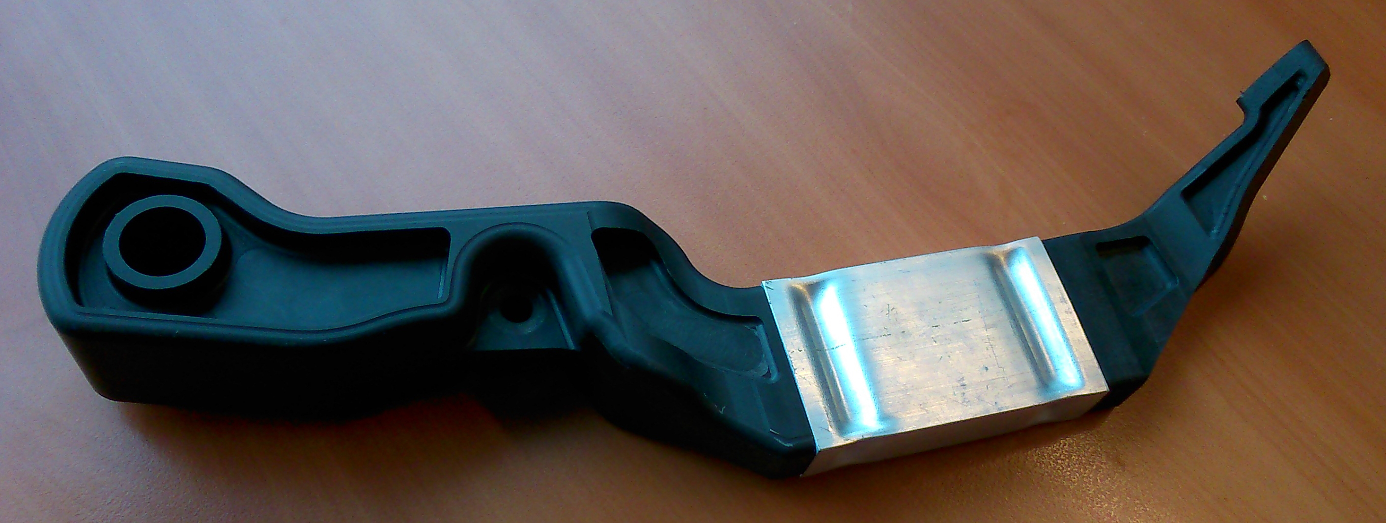
Figure 16: Prototype of the hybrid metal-composite brake pedal (Source: Toolpresse, Portugal [6])
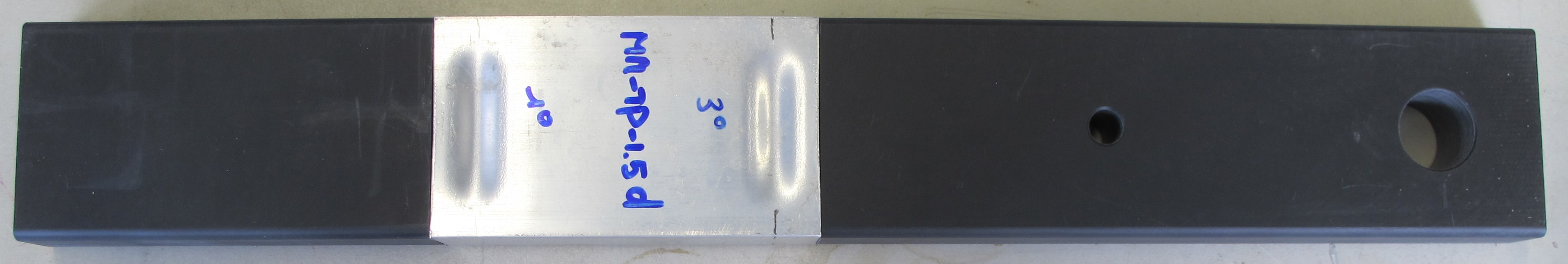
Figure 17: Demonstrator of the hybrid metal-composite brake pedal (Source: Belgian Welding Institute, Belgium) [5]
A cross section of the demonstrator for the hybrid metal-composite brake pedal is shown in Figure 18. The deformation of the aluminium tube into the groove of the composite is clearly illustrated. This mechanical interlock partially contributed to the transferable forces achieved, which are graphically shown in Figure 19 as a function of the discharge energy necessary to create the joint. The maximum transferable force was achieved at an optimal discharge energy, after which the transferable force again decreased. This illustrates that there was a trade-off the different phenomena that took place during tensile testing. On the one hand, the deformation of the aluminium tube into the groove contributed to the increase of the transferable force, due to the larger mechanical interlocking achieved. On the other hand however, necking of the aluminium tube during tensile testing, could have resulted in a decrease in the transferable force.
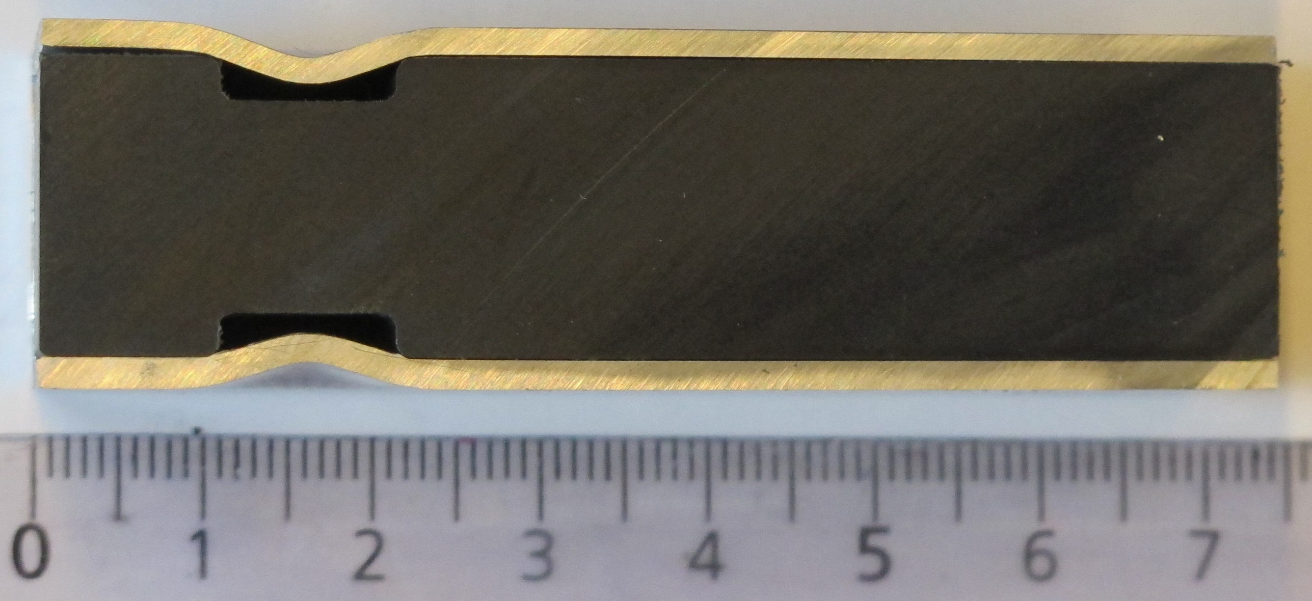
Figure 18: Cross section of the demonstrator for the hybrid metal-composite brake pedal (Source: Belgian Welding Institute, Belgium) [5]

Figure 19: Hybrid metal-composite brake pedal: maximum transferable force versus applied discharge energy (Source: Belgian Welding Institute, Belgium) [5]
Hybrid metal-composite shock absorber
Tenneco Belgium is a manufacturer of shock absorbers, consisting of a connection of 2 tubular components which currently made out of steel. These existing parts are produced using conventional welding techniques. In the MetalMorphosis project, the redesigned part consisted out of a steel and composite component. The hybrid steel-composite joint must fulfill the standard Tenneco requirements, namely that the different elements must be considered as structural components. It is moreover necessary that they are gas tight, withstand high pressure and temperatures and exhibit a minimum of bending.
The driving force behind introducing composites in the shock absorber is the targeted weight decrease and easy integration in existing process lines. The state-of-the-art steel shock absorber has a weight of 1,6 kg and the partial replacement by a composite should result in a 15% weight decrease. The use of composite should preferably without product cost increase. Based on commercial considerations, a total product cost increase of 1 to 3 €/ kg saved weight is however allowable (including tooling costs, required modification of process line, investments, manpower, etc.)
Conclusion
The MetalMorphosis research project aimed at developing innovating joining processes for composites and metals, based on the electromagnetic pulse technology. This promising technology allows a range of new hybrid metal-composite components to be manufactured, and that matches the current trend towards lightweight materials in the automotive industry. Based on the novel insights acquired, demonstrator parts specifically targeted at the automotive market were developed, namely a hybrid metal-composite brake pedal and shock absorber.
More information on the MetalMorphosis project and an overview of the results achieved can be found at: http://www.metalmorphosis.eu/
The specialised and multidisciplinary MetalMorphosis consortium consisted of 9 European partners: the Belgian Welding Institute (Belgium) [5], Tenneco Automotive Europe (Belgium) [7], POYNTING (Germany) [4], CENTIMFE (Portugal) [8], Toolpresse (Portugal) [6], Cidaut (Spain) [9], IK4-IDEKO (Spain) [10], STAM (Italy) [11] and Regeneracija (Slovenia) [12].
This project has received funding from the European Union’s Seventh Framework Programme (FP7) for research, technological development and demonstration under grant agreement nr 609039.
More information
References
[1]: Superlight Car Life Cycle Assessment. Available online: http://www.worldautosteel.org/life-cycle-thinking/case-studies/super-lig...
[2]: BMW i8 – BMW blog First Drive. Available online: http://www.bmwblog.com/2013/08/13/bmw-i8-bmwblog-first-drive/
[3]: Institut für Umformtechnik und Leichtbau, Technische Universität Dortmund, Germany. Available online: http://www.iul.eu/iul/index.php/en/
[4]: Poynting GmbH, Germany. Available online : http://www.poynting.de/de/homepage.html
[5]: Belgian Welding Institute, Belgium. Available online : https://www.bil-ibs.be/en/research
[6]: Toolpresse, Portugal. Available online: http://www.toolpresse.pt/
[7]: Tenneco Automotive Europe, Belgium. Available online : http://www.tenneco.com/europe/
[8]: Centimfe, Centro Technologico de Industria de Moldes, Portugal. Available online : http://www.centimfe.com/index.php/en/
[9]: Foundation Cidaut, Transport and Energy Research and Development, Spain. Available online : http://www.cidaut.es/en/
[10]: IK4-IDEKO, Research Alliance, Spain. Available online : http://www.ideko.es/
[11]: Stam, industrial research, Italy. Available online : http://www.stamtech.com/
[12]: Regeneracija, Slovenia. Available online :http://www.regeneracija.hr/index.php/en/