Friction spot joining
Process principles
Friction spot welding is a solid state welding process, suitable for spot joining lightweight low-melting point materials, such as aluminium and magnesium alloys. The process is carried out using a tool to create a connection between sheets in the overlap configuration, by means of frictional heat and mechanical work.
A three-component tool comprising a pin, sleeve and clamping ring is used to join two or more sheets (see Figure 1). The clamping ring initially fixes the sheets against a backing plate, while the pin and sleeve begin to rotate in the same direction, while pressing on the upper surface (Figure 1a). The rotating pin and sleeve are moved in opposite direction of each other (one is plunged into the material while the other moves upwards), creating a cavity inside the sleeve, where the plasticised material through frictional heat is accommodated (Figure 1b). After reaching the pre-set plunge depth, the pin and sleeve return to their initial position, forcing the displaced plasticised material to completely refill the keyhole (Figure 1c). Finally, the tool rotation is stopped and the tool is withdrawn from the joint, leaving a flat surface with minimum material loss (Figure 1d).
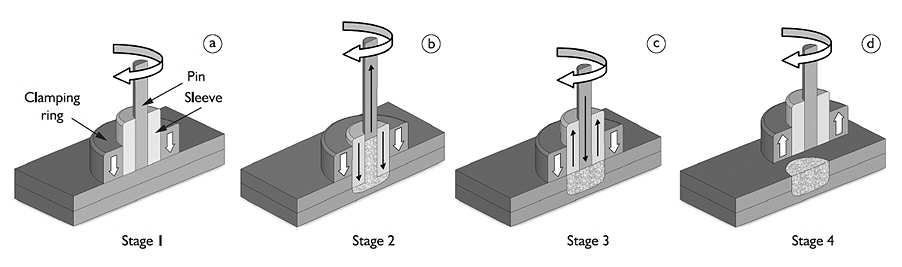
Figure 1: Working principle of friction spot welding
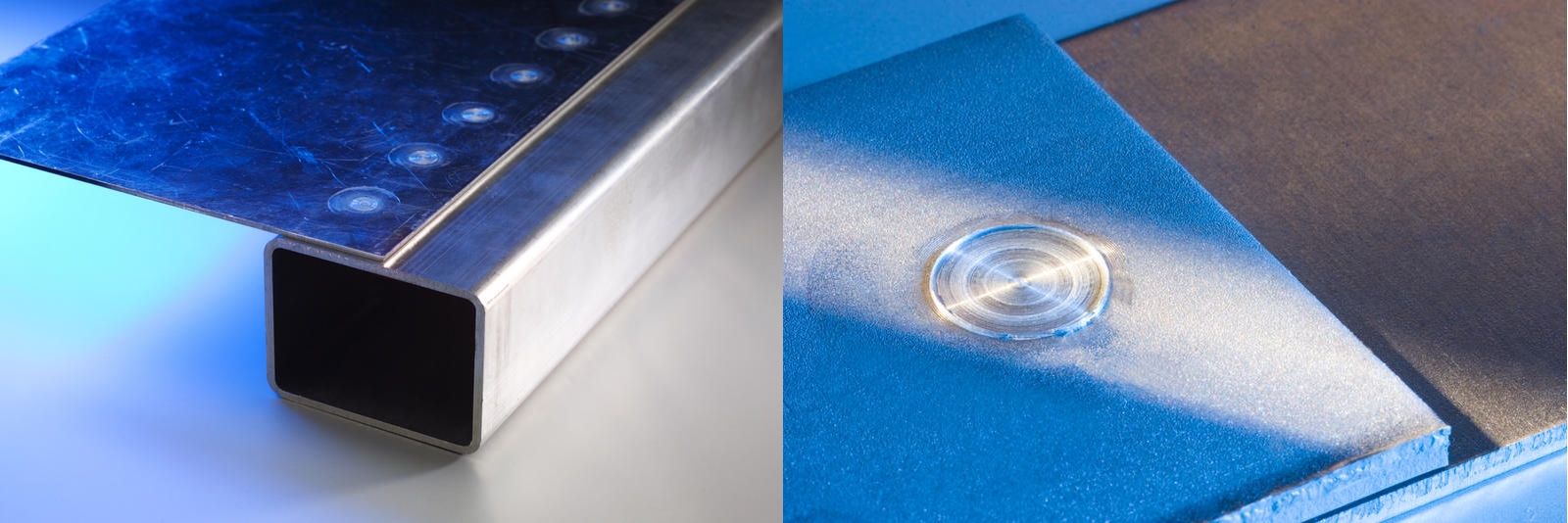
Figure 2: Example of a friction spot welded components (Source: Riftec gmbh)
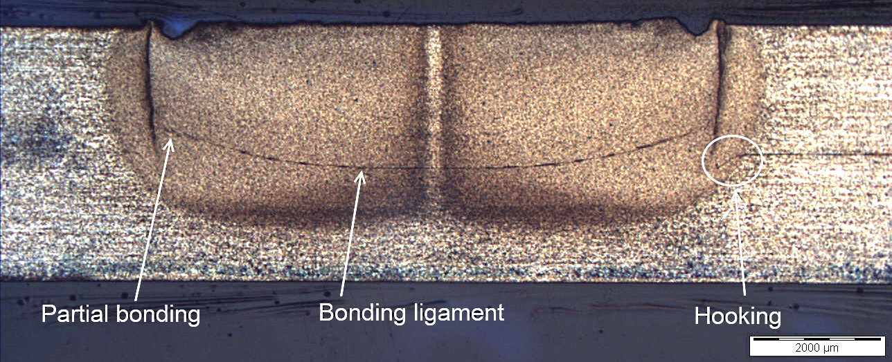
Figure 3: Typical cross section of a weld in aluminium EN AW-6082-T6 (sheet thickness: 2 mm)

Figure 4: Connection of aluminium EN AW-6082 and galvanised steel
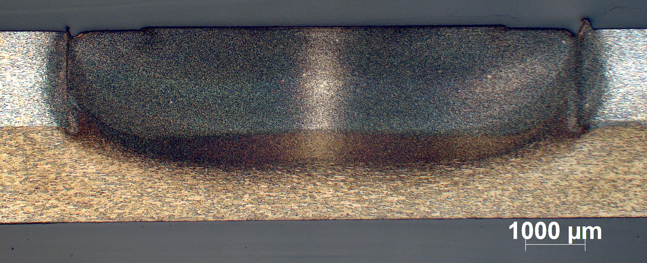
Figure 5: Cross section of a weld between aluminium EN AW-2024 and 7475
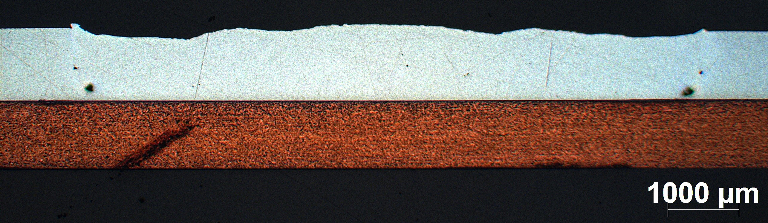
Figure 6: Cross section of a weld between aluminium and copper (EN AW-1050 - ETP-Cu)
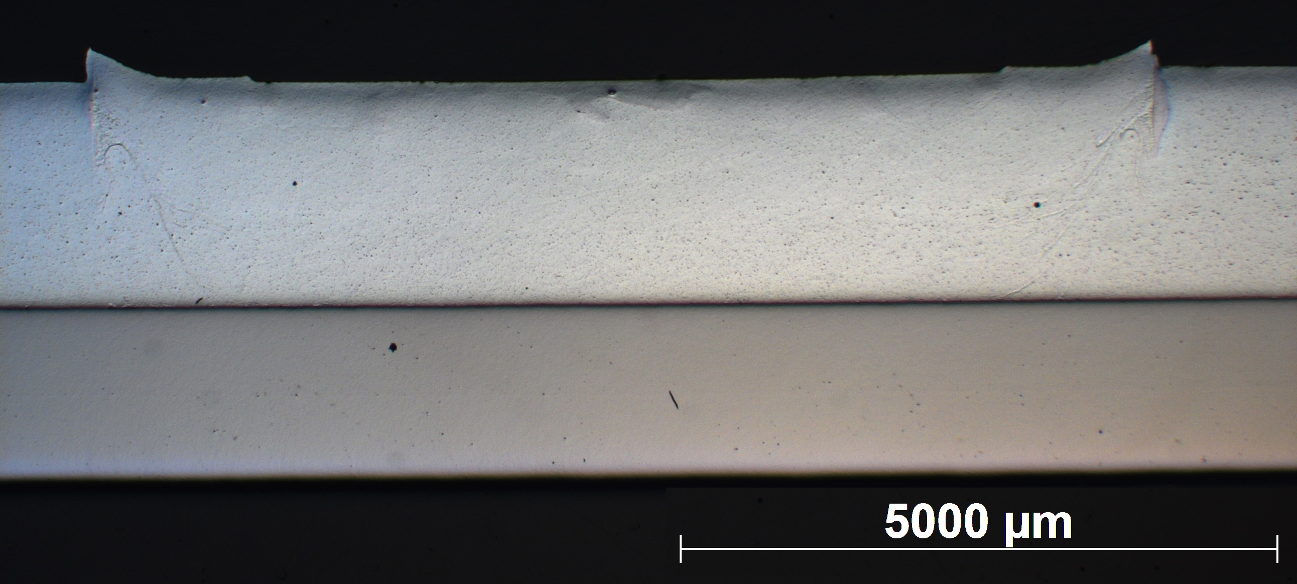
Figure 7: Unetched cross section of an aluminium-steel weld
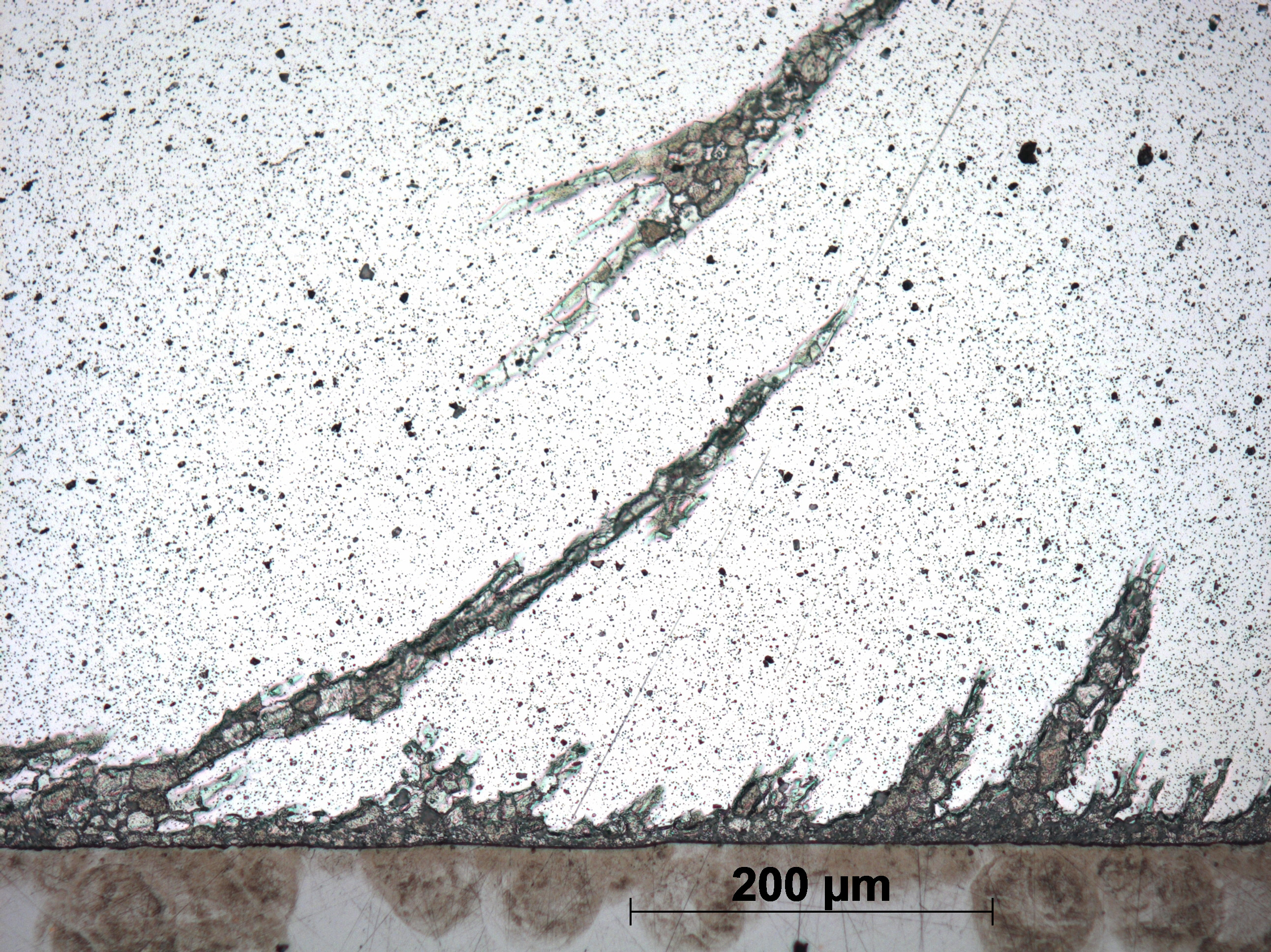
Figure 8: Detail of figure 7: Weld interface between aluminium and steel (Source: Belgian Welding Inst.)
Equipment
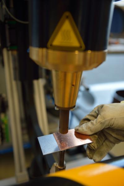
BWI possesses a versatile welding machine, that can be used to perform feasibility studies for potential industrial applications.
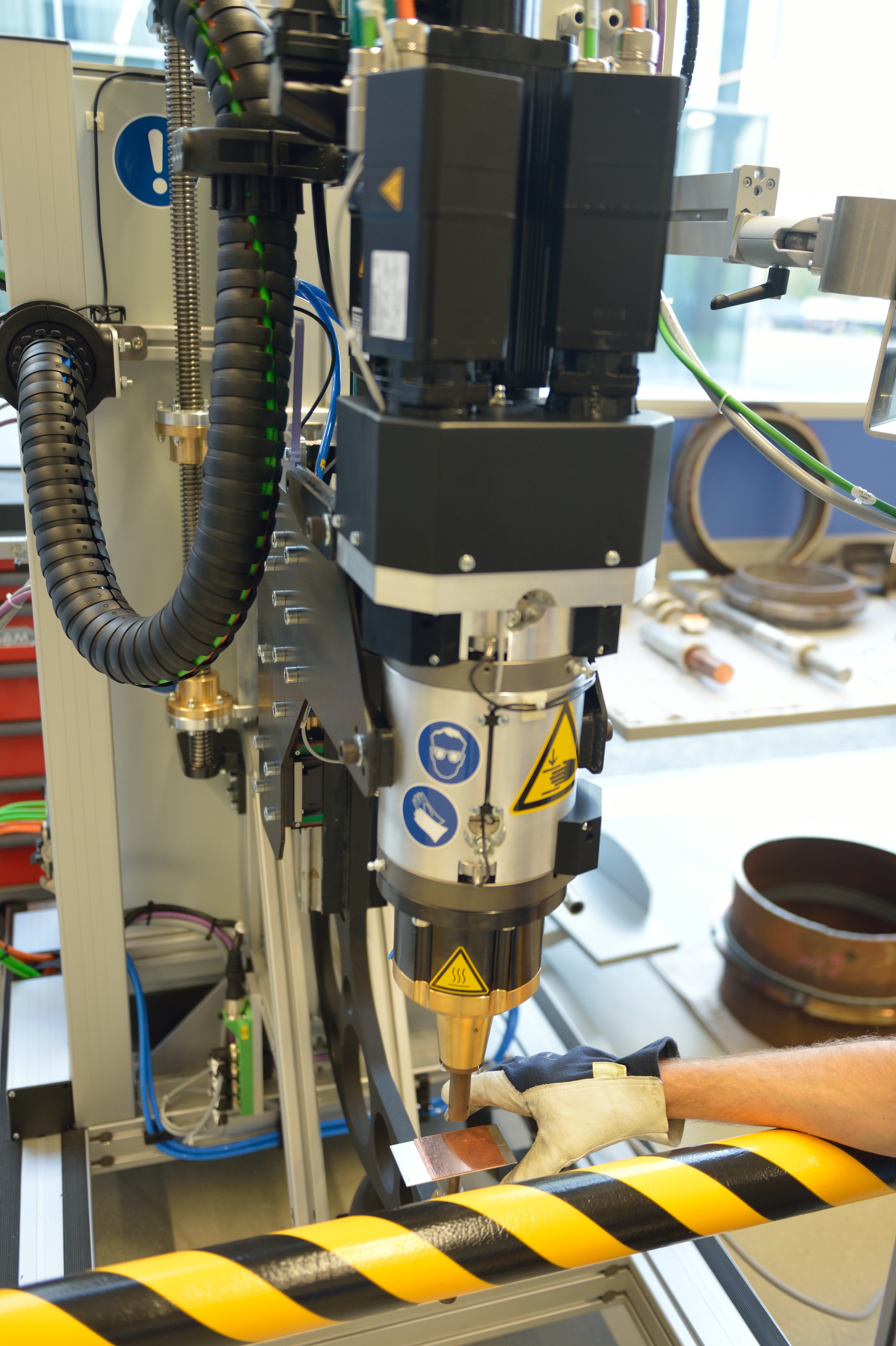
Figure 9: Welding equipment available at BWI
dr. ir. Koen Faes